|

|
|
Rubber flexible joint Spherical type
TOZENFLEX
|
Spherical shape is most popular type of rubber flexible joint for vibration isolation
• Unique spherical shape
• Outstanding pressure-resistance performance
• Unified face-to-face dimension
Application
Vibration absorption of pumps and equipment, absorption of piping eccentricity, expansion and compression
Installation
Pumps, chillers, receiving tanks, high-set water tanks, etc.

Low reaction force
Superb vibration absorption effect with reduce load and stress on equipment and piping.
Unique spherical shaped form
Slim arch shape avoids the contact of rubber body with bolt head.
Excellent pressure resistance
Spherical type rubber flexible joint has outstanding performance in pressure resistance.
Available for slurry
Smooth interior surface (buried rubber type) is available upon request for sewage or fluid
with particles tend to precipitate or accumulated.
Face-to-face dimension is standardized
Face-to-face dimension is identical for 32A-200A. It is convenient for design when compared
with others different face-to-face dimension by size.
| Applications |
|
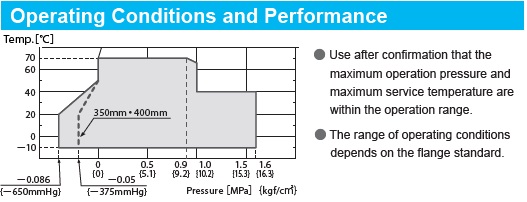
● This product is mainly applicable for air conditioner, water supply and drainage, and sanitation facilities around piping systems in commercial and industrial buildings and plants.
● Applicable fluids are exclusively water including cold water, warm water, cooled water, and seawater, etc.
● This product cannot be used for pool water, oil, or boiled water.
|
| |
|

|
|
|
|
Structure
|
|

|
|
|
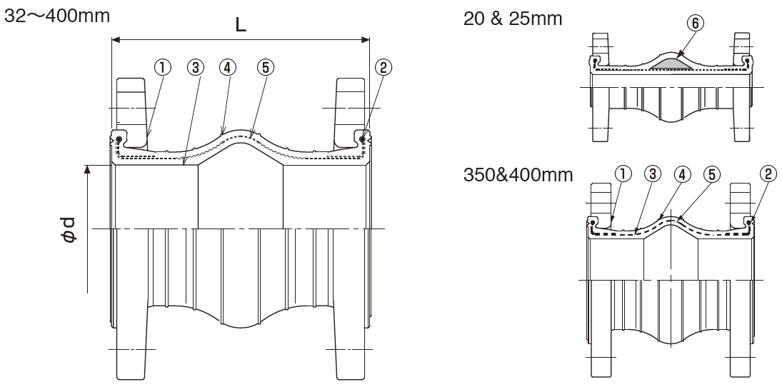
No.
|
Parts |
Material |
| 1 |
Flange |
Mild Steel / Ductile Iron |
| 2 |
Reinforcing Ring |
Carbon Steel |
| 3 |
Inner Rubber |
Synthetic Rubber
|
| 4 |
Outer Rubber |
Synthetic Rubber
|
| 5 |
Reinforcing Cord |
Synthetic Fiber |
| 6 |
Filler |
Special High-polymer Rubber |
| |
|
|
|
|
● Flanges with mild steel and ductile iron in JIS10K, ANSI150, PN16 are standard.For other flanges, please consult us.
● Flange material can be changed to SUS304 and SUS316.
● ANSI flange type for 20&32mm is not produced.
● The flange material for ANSI150 25mm and PN16 20&25mm is mild steel only.
● The flange material for 350&400mm is mild steel only.
● Like the drawing on left, the inner rubber for 20&25mm is flat type.
● For 32 ~ 300mm, the inner rubber flat type is also possible.
|
| |
| Dimensions and Allowable Movements |
| Nominal Dia. |
Dimension [mm] |
Mass
[Kg] |
Allowable Movement [mm] |
Installation Tolerances [mm] |
| mm |
inch |
L |
φd |
T.M |
A.E |
A.C. |
A.M. |
T.M |
A.E |
A.C. |
A.M. |
| 20 |
3/4 |
140 |
25 |
1.1 |
10 |
5 |
10 |
15° |
4 |
3 |
6 |
7.5° |
| 25 |
1 |
140 |
25 |
1.6 |
10 |
5 |
10 |
15° |
4 |
3 |
6 |
7.5° |
| 32 |
1 1/4 |
150 |
40 |
2.0 |
20 |
10 |
20 |
15° |
8 |
3 |
6 |
7.5° |
| 40 |
1 1/2 |
150 |
40 |
2.1 |
20 |
10 |
20 |
15° |
8 |
3 |
6 |
7.5° |
| 50 |
2 |
150 |
50 |
2.7 |
20 |
10 |
20 |
15° |
8 |
3 |
6 |
7.5° |
| 65 |
2 1/2 |
150 |
65 |
3.7 |
20 |
10 |
20 |
15° |
8 |
3 |
6 |
7.5° |
| 80 |
3 |
150 |
75 |
3.8 |
20 |
10 |
20 |
15° |
8 |
3 |
6 |
7.5° |
| 100 |
4 |
150 |
100 |
4.6 |
20 |
15 |
20 |
15° |
8 |
3 |
6 |
7.5° |
| 125 |
5 |
150 |
125 |
6.6 |
20 |
15 |
20 |
15° |
8 |
3 |
6 |
7.5° |
| 150 |
6 |
150 |
150 |
9.1 |
20 |
8 |
15 |
15° |
8 |
3 |
6 |
7.5° |
| 200 |
8 |
150 |
200 |
12 |
20 |
8 |
15 |
15° |
10 |
3 |
6 |
7.5° |
| 250 |
10 |
200 |
250 |
20 |
25 |
15 |
20 |
15° |
10 |
3 |
6 |
7.5° |
| 300 |
12 |
200 |
300 |
22 |
25 |
15 |
20 |
15° |
10 |
3 |
6 |
7.5° |
| 350 |
14 |
200 |
350 |
30 |
25 |
15 |
20 |
15° |
10 |
3 |
6 |
7.5° |
| 400 |
16 |
200 |
400 |
42 |
25 |
15 |
20 |
15° |
10 |
3 |
6 |
7.5° |
| |
|
|
|
|
|
|
|
|
|
|
|
|
|
・A.C.: Axial Compression, A.E.: Axial Elongation, A.M.: Angular Movement, T.M.: Transverse Movement.

・Mass indicates only the case with JIS 10K (Ductile Iron) flanges. However,mass for 350&400mm is with JIS 10K(Mild Steel)flange.
・Tolerances for installation are included in the allowable movements (Allowable movements = Tolerances for installation + Operating movements).
・Please note that the information in the above table is for single movement only.
In case of complex movements, please do adjustment by using the following formula.
C.A.E. (C.A.C.) = A.A.E.(A.A.C.) × {1-(T.M./A.T.M+A.M./A.A.M)}
C.A.E. (C.A.C.): Correct Elongation Movement (Correct Compression Movement)
A.A.E. (A.A.C.): Allowable Elongation Movement (Allowable Compression Movement)
A.T.M.: Allowable Transverse Movement
A.A.M.: Allowable Angular Movement
Example: In case of 100mm joint, if 10mm transverse movement is needed,
then the correct elongation should be: C.A.E = 15 × {1- (10/20+0/15)} = 7.5mm
・There is reaction force from rubber joints due to the load of the internal pressure, so during the installation, please use the metal fittings to fix the pipe tightly to ensure the joints work efficiently. In case the pipe cannot be fixed tightly, please use the control unit for the joints.
|
Precaution for fixing of pump suction side
●When water is pumped up from a water tank which is placed on a level lower than the pump, and for pipelines in
which there is always negative pressure developed, trouble can occur. For the above situation, it is
recommended to use Tough-Boy or LS connectors (for suction).
Note:The contents of this catalogue are subject to change without notice.
and click catalogue request button, and the page you checked can be all downloaded.